Pinmi
Get a Quote
Pinmi
Integrated Continuous Casting & Rolling Solution for 8mm Low-Oxygen Bright Copper Rod
This 35 TPH copper rod production line makes Φ8 mm low‑oxygen bright copper rods for wires, cables and conductors. It integrates continuous casting, rolling, non-acid cleaning, cooling, coating and coiling. Equipped with a 2440 mm casting wheel and 11-stand mill, it delivers stable continuous production for large copper rod plants via PLC/HMI process control.
From molten copper to finished 8mm rod coils, the line is engineered as one connected production system. The equipment sequence is matched around casting stability, rolling reduction, rod surface treatment, coil formation and line-wide speed coordination rather than treating each machine as an isolated unit.
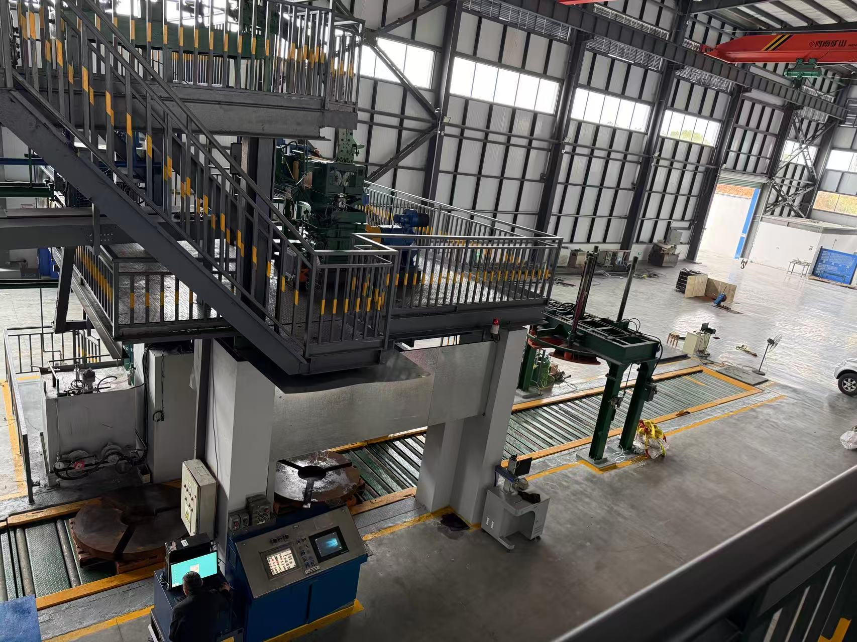
The reference line is configured to produce Φ8 mm electrical-grade low-oxygen bright copper rod at 35 TPH. The continuous caster forms a 5430 mm² copper cast bar, which is prepared and progressively reduced through the roughing and finishing mills. After rolling, the rod passes through non-acid cleaning, cooling and protective coating before automatic coil formation and downstream transfer.
Molten Copper → Continuous Casting → Cast-Bar Handling → Rough Rolling → Intermediate Shearing → Finish Rolling → Non-Acid Cleaning & Cooling → Protective Coating → Coiling → Coil Transfer
Production Line
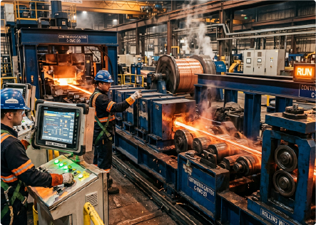
Production Line
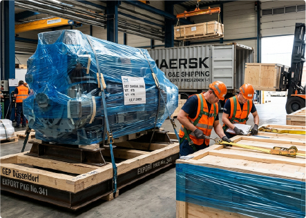
Production Line
| Equipment | Role in the Solution |
|---|---|
| Five-Wheel Continuous Casting Machine | Converts molten copper into a continuous 5430 mm² cast bar with controlled cooling and stable casting conditions. |
| Rotary Shear & Scrap Handling | Cuts cast bar during startup or abnormal rolling conditions and allows casting continuity while downstream equipment is cleared. |
| Mobile Hydraulic Shear | Supports cast-bar cutting and removal of partially rolled scrap in the casting and rolling areas. |
| Cast-Bar Preparation Unit | Guides and prepares the cast bar before entry into the rolling section. |
| 3-Stand Roughing Mill | Performs the initial reduction of the cast bar and prepares it for finish rolling. |
| Intermediate Rotary Shear | Provides cutting and discharge between roughing and finishing sections when required. |
| 8-Stand Finishing Mill | Progressively rolls the material to the specified Φ8 mm finished copper rod. |
| Non-Acid Cleaning Line | Cleans and cools the finished rod with an alcohol-based cleaning solution before coiling. |
| Rod Cleaning, Cooling & Coating System | Reduces surface oxide, cools the rod and applies a protective coating to delay oxidation during storage and transport. |
| Copper Rod Coiling System | Forms the finished rod into constant-diameter coils and supports automatic coil change by selected coil weight. |
| Roller Conveyor System | Transfers completed copper rod coils toward downstream handling and packing. |
| Lubrication & Emulsion Systems | Provide lubrication and cooling media for roughing and finishing mill operation. |
| Process Monitoring & Data Acquisition | Provides real-time monitoring, historical trends, alarms, reporting and networked process data. |
| Electrical Control System | Coordinates drives, PLC, HMI, sensors, interlocks and line-wide speed synchronization. |
The solution follows a continuous process route designed to maintain material flow and stable production from casting through finished coil handling.
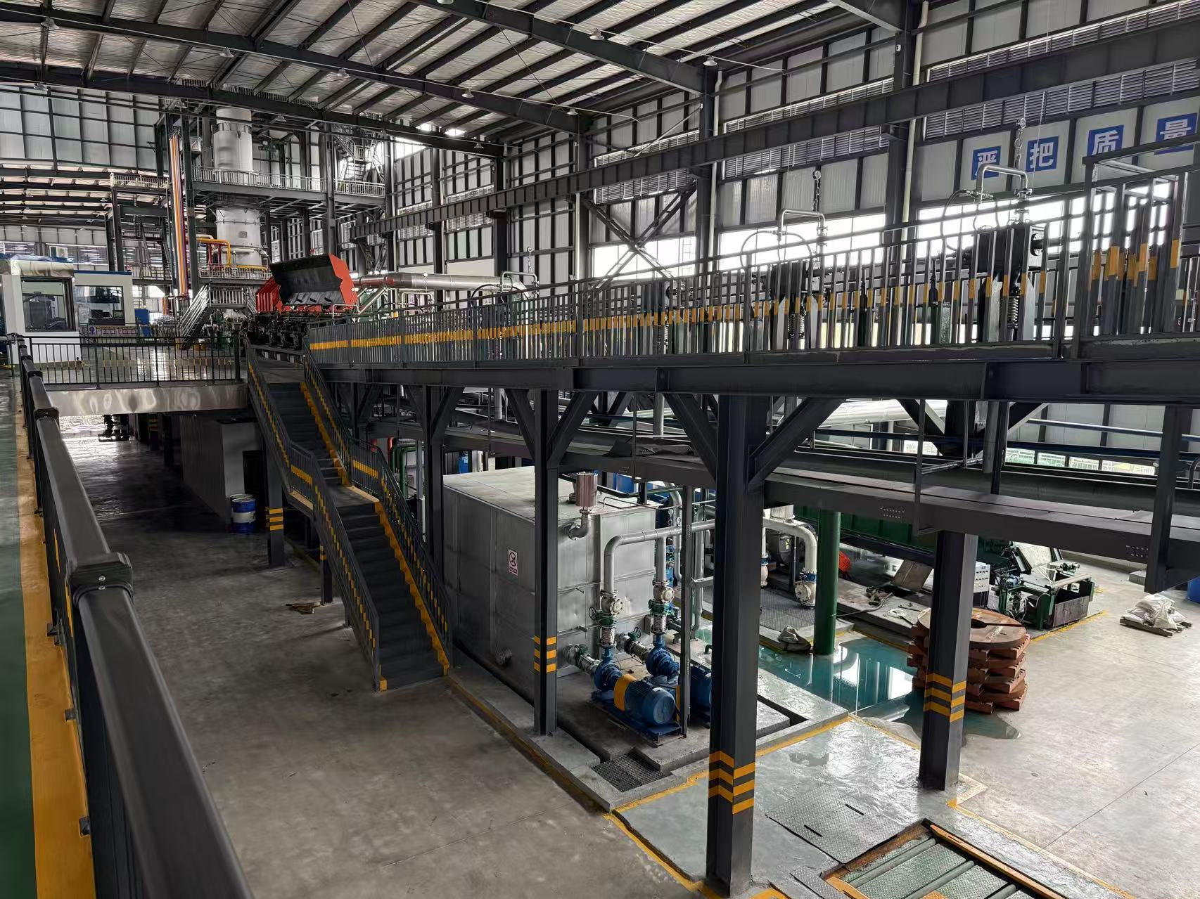
Molten copper is introduced into the five-wheel continuous caster. The casting wheel and steel belt form the mold, while zoned cooling controls solidification and mold temperature distribution. Automatic cast-bar loop control coordinates the caster with the rolling section
During startup or abnormal conditions, the rotary shear can continuously cut cast bar until rolling requirements are met. A mobile hydraulic shear supports cast-bar clearing and removal of partially rolled scrap.
The cast bar enters three individually driven roughing stands. The no-twist roughing arrangement reduces the cast-bar section and prepares the material for the finishing mill. Adjustable guides and fault detection support stable transfer between stands.
Between roughing and finishing, the intermediate shear can remove material during a finishing-mill fault while allowing the roughing section to continue operating. The transfer section also supports tension control between rolling stages.
Eight individually driven finishing stands progressively roll the incoming material to Φ8 mm copper rod. The cantilever no-twist design, adjustable roll gap and guide system are intended to support stable rod dimensions and smooth transfer between stands.
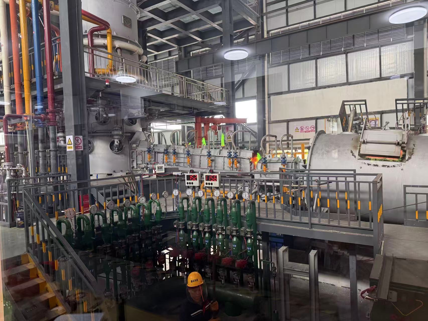
The reference configuration uses a 2440 mm casting wheel, a 5430 mm² cast-bar section and an 11-stand rolling arrangement consisting of one 412 mm roughing stand, two 305 mm roughing stands and eight 204.5 mm finishing stands. Finished coils are designed around a 1600 mm outer diameter, 800 mm inner diameter and a reference coil weight of 2–4 tons.


Need answers for copper production‑line, furnace configuration or custom‑project concerns? Send us an inquiry to get expert‑tailored suggestions.

Share your capacity, raw material and site conditions — we'll come back with a process route, equipment selection and a turnkey path to production.


No.310–311 National Road, Quanshan District, Xuzhou City, China