Pinmi
Get a Quote
Pinmi
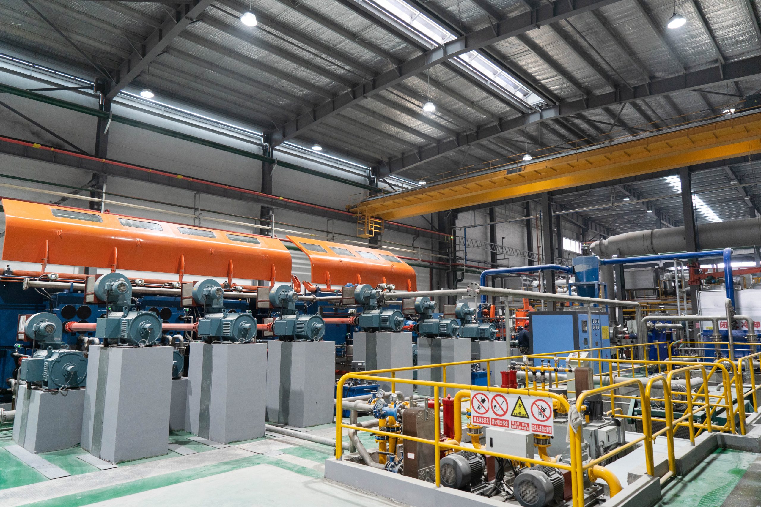
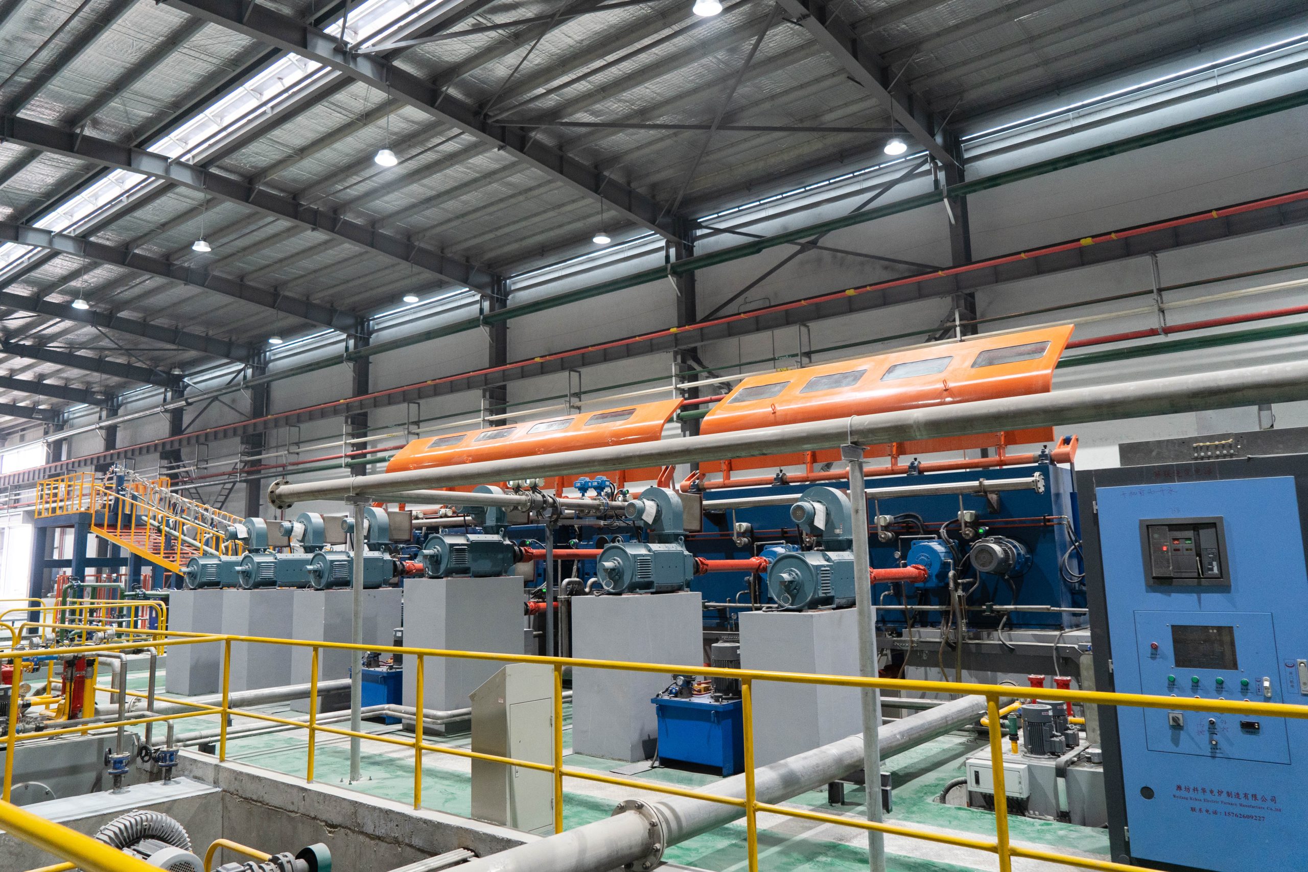
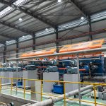
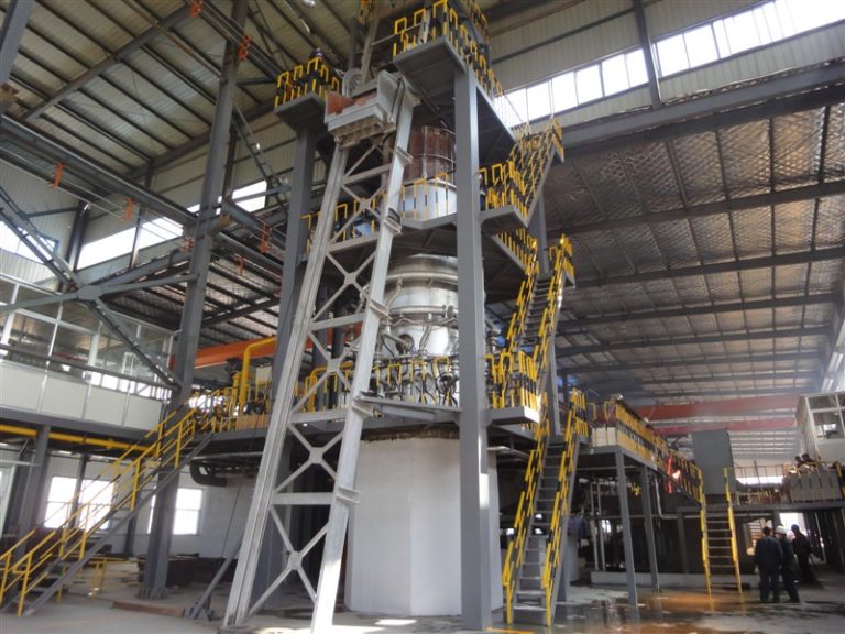
The copper CCR line connects molten copper preparation, continuous casting and rolling in one production flow. This reduces intermediate handling, avoids repeated reheating and improves continuous production efficiency.
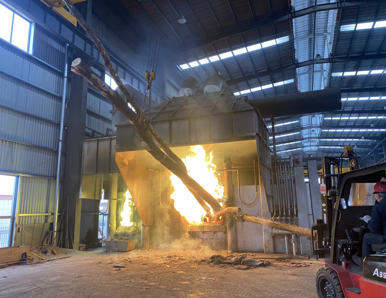
The furnace system is designed to supply stable molten copper to the casting process. With controlled melting, holding, launder heating and cooling, the finished copper rod can achieve consistent diameter, surface quality and internal structure.
The documented shaft furnace has a maximum melting rate of 18 t/h and a normal continuous production rate of 15-16 t/h. This provides a solid molten copper supply basis for industrial copper rod manufacturing.
Continuous casting and rolling reduces heat loss between process stages. The shaft furnace uses high-power burners and controlled air-natural gas ratio, with normal continuous natural gas consumption of 30-40 Nm3 per ton of copper under the documented conditions.
The furnace system can be equipped with Siemens PLC and touch screen operation. Natural gas flow, air flow, fan frequency, temperature, pressure, CO analysis and alarms can be monitored to support stable production control.

Copper Rod Production Plants

Wire and Cable Manufacturing Factories

Electrical Conductor Production

Power Cable Industry
Copper Wire Drawing Plants
Copper Alloy Rod Processing
Non-Ferrous Metal Processing Plants
The system is delivered as a sequence of coordinated stations, each built and tested in-house before shipment.

16‑18t/h shaft furnace with silicon nitride bonded SiC lining, multi‑row premixed natural‑gas burners for continuous copper melting.

Stabilizes molten copper temperature & flow; hydraulic tilting output for steady feeding to caster.

Insulated closed launders with heating burners, minimizes heat loss and molten copper oxidation during transfer.

Forms molten copper into continuous cast bar; casting wheel & structure customized for target capacity.

Trims and guides cast bar, guarantees stable and continuous bar feeding into rolling mill.

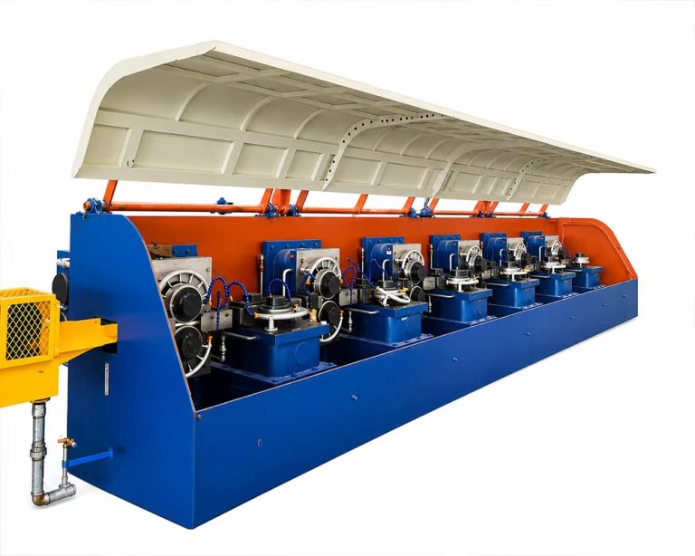
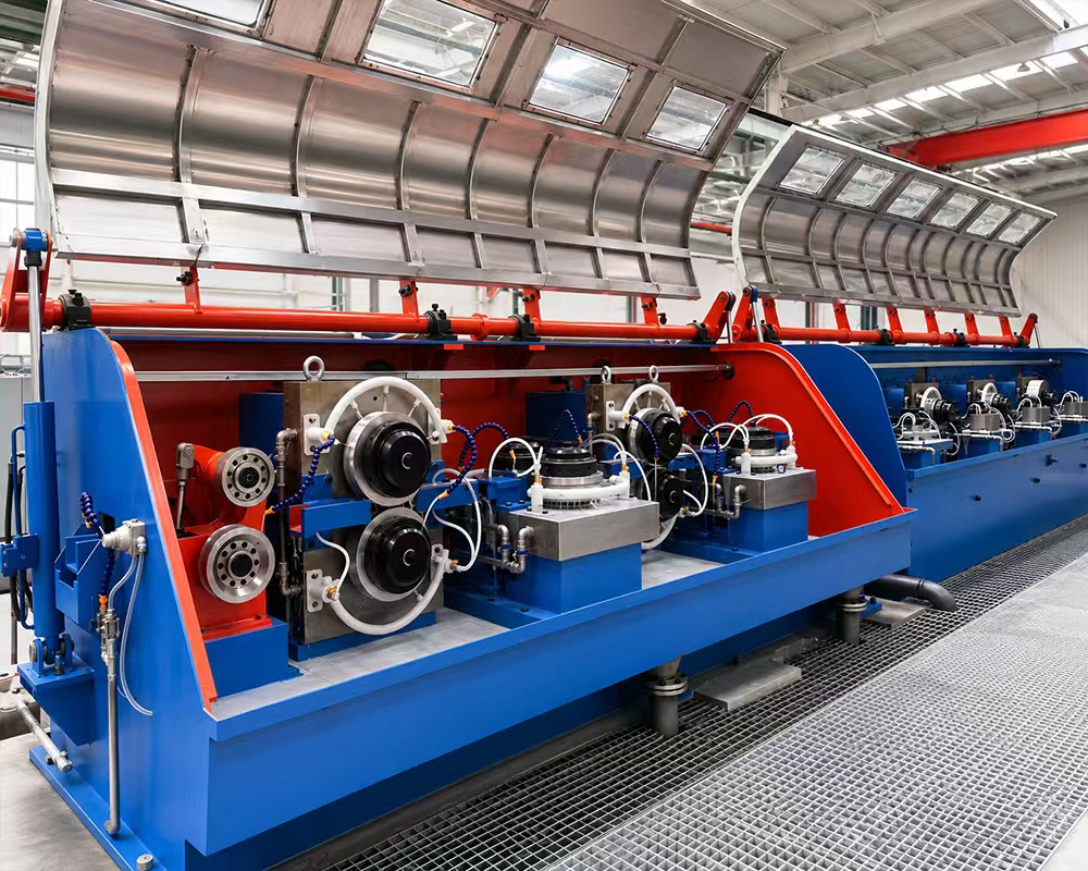
Heavy‑duty rolling stands, step‑by‑step bar reduction to finished copper‑rod dimension.

Circulating water cooling plus lubrication system, protects rolls, improves rod surface quality.

Single / double coiler option, coils finished copper rod for downstream drawing & cable production.
Reference size cover most projects. Intermediate capacities and custom configurations are engineered on request.
| Equipment | Main Function |
| Copper Melting Furnace | Vertical shaft furnace for melting copper cathode and qualified clean copper return materials. The documented system uses silicon nitride bonded silicon carbide lining and two rows of burners. |
| Holding Furnace | 20T hydraulic tilting holding furnace used to stabilize molten copper temperature and flow before the casting machine. |
| Continuous Casting Machine | Casts molten copper into a continuous copper bar for rolling. Casting structure and wheel size are customized according to line capacity. |
| Feeding and Shearing System | Guides and prepares the cast bar for smooth entry into the rolling mill, supporting continuous line operation. |
| Continuous Rolling Mill | Rolls the cast copper bar into the required copper rod diameter through multiple rolling stands. |
| Cooling and Lubrication System | Controls rod and roll temperature, reduces friction, protects rolling tools and improves rod surface quality. |
| Coiling Machine | Collects finished copper rod into coils for storage, transport or further wire drawing. |
| Hydraulic System | Provides motion control for the holding furnace tilting mechanism and selected auxiliary equipment. |
| Electrical Control Cabinet | Controls motors, fans, drives, sensors, alarms and operating interface for the production line. |
| PLC Control System | Siemens PLC/HMI can monitor furnace parameters, gas-air ratio, CO analysis, fan frequency, line speed and alarms according to configuration. |
| Auxiliary Equipment | Includes charging system, closed launders, slag removal groove, cooling water circuit, compressed air system, combustion valve groups and safety interlocks. |
Reference values — final parameters are confirmed during process design based on raw material, site conditions and product standard. Replace with your confirmed datasheet values before publishing.
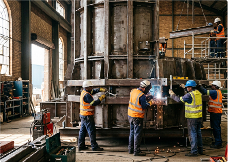
workshop
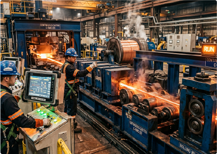
trial run
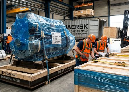
container load
workshop

Share your capacity, raw material and site conditions — we'll come back with a process route, equipment selection and a turnkey path to production.


No.310–311 National Road, Quanshan District, Xuzhou City, China
Check our FAQs below, or reach out to our team for tailored answers and project quotation.
Get a Quote