Pinmi
Get a Quote
Pinmi
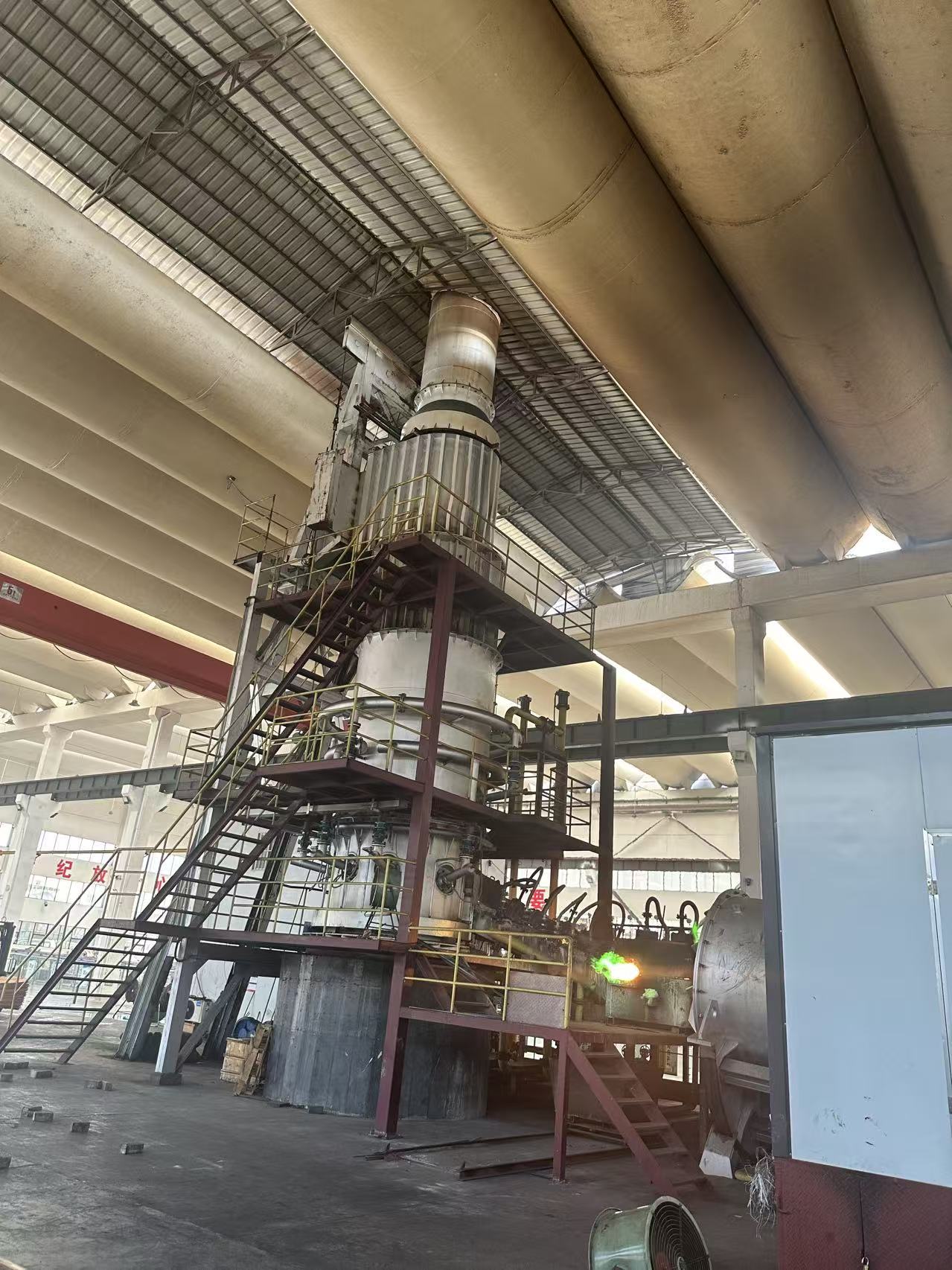
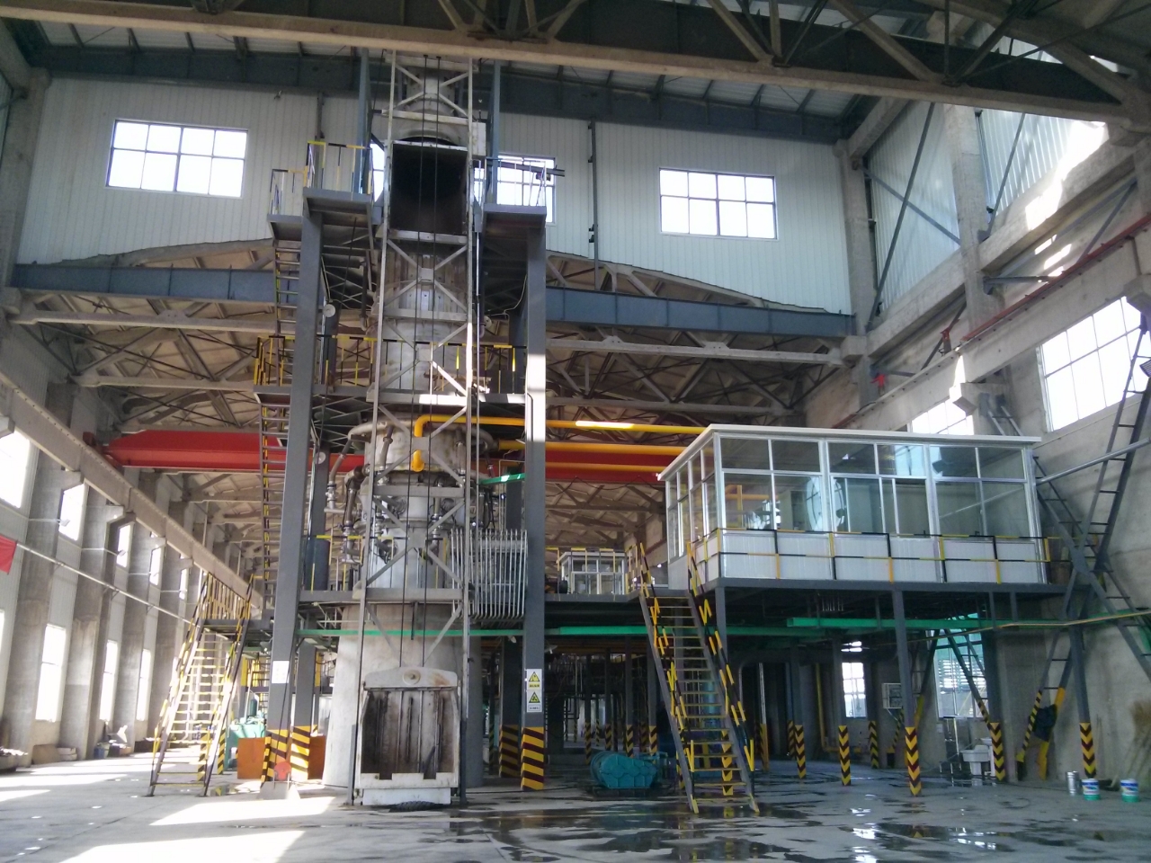
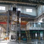
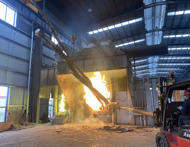
The holding furnace balances molten copper temperature and flow fluctuations between the melting furnace and casting equipment. This helps the casting package or casting machine receive stable and high-quality molten copper.
The furnace chamber temperature is measured online by thermocouple, making it easier for operators to monitor and control daily heating and casting temperature. PLC/HMI control can be configured according to project requirements.
The steel furnace body, refractory lining and insulation structure help reduce heat loss during molten copper holding. Stable insulation supports lower energy consumption and more consistent process conditions.
The documented furnace uses silicon nitride bonded silicon carbide brick for the furnace lining and corundum refractory material for the furnace door lining. This structure is suitable for long-term high-temperature molten copper service.
The inlet and outlet are positioned at the rotation center of the furnace body, while hydraulic cylinders support fine tilting and continuous tilting. This design helps control molten copper flow to the casting process.

Copper Rod Production Lines

Copper CCR Lines

Copper Continuous Casting Lines

Copper Alloy Production
Wire and Cable Manufacturing Factories
Copper Melting and Holding Workshops
Copper Cathode Melting Projects
Electrical Conductor Production
The system is delivered as a sequence of coordinated stations, each built and tested in-house before shipment.

Arc‑shaped heavy‑duty steel shell with roller base, supports refractory lining and hydraulic tilting movement.

Silicon‑nitride‑bonded SiC brick for hearth; corundum lining for furnace door, excellent high‑temperature copper‑liquid resistance.

Two natural‑gas burners plus air‑gas mixing unit, maintains constant molten‑copper holding temperature.

Hydraulic cylinder power unit, tilting angle>90°, emergency tilting function for stable molten copper discharging.

Inlet & outlet arranged at furnace rotation center for steady, disturbance‑free copper liquid transfer.

Cylinder‑driven furnace door, reliable sealing, convenient opening‑closing for operation & inspection.

Thermocouple real‑time temperature monitoring, feeds data to control cabinet for process adjustment.

Monitors temperature, burner status, hydraulic action and system alarms; manual / semi‑auto / auto modes optional.
Reference size cover most projects. Intermediate capacities and custom configurations are engineered on request.
| Equipment | Main Function |
|---|---|
| Copper Holding Furnace Body | Steel furnace body designed for molten copper holding, temperature stabilization and controlled discharge. |
| Heating System / Burner System | Two burners and matched air-gas mixing system maintain the required holding temperature in the documented configuration. |
| Refractory Lining and Insulation Structure | Silicon nitride bonded silicon carbide brick lining and insulation materials protect the furnace body and reduce heat loss. |
| Molten Copper Inlet and Outlet System | Inlet and outlet located near the rotation center help stabilize molten copper transfer between furnace, launder and casting equipment. |
| Temperature Measuring System | Thermocouple online measurement provides furnace temperature data for operating control and daily heating management. |
| Electrical Control Cabinet | Controls fans, motors, hydraulic system, sensors, alarms and operating interface according to project configuration. |
| PLC Control System | PLC/HMI control can be configured for temperature monitoring, burner control, fan control, alarms and production status display. |
| Flow Channel / Launder System | Refractory-lined upper and lower launders transfer molten copper between the shaft furnace, holding furnace and casting machine. |
| Cooling System | Cooling water or auxiliary cooling systems can be designed according to equipment structure and site requirements. |
| Exhaust or Flue Gas System | Flue gas and combustion exhaust arrangement is configured according to furnace layout and local project conditions. |
| Auxiliary Equipment | Can include pneumatic door control, hydraulic station, gas valve groups, fan system, safety interlocks, platforms and installation materials based on project scope. |
Reference values — final parameters are confirmed during process design based on raw material, site conditions and product standard. Replace with your confirmed datasheet values before publishing.
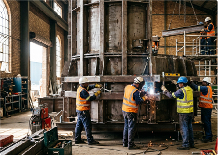
workshop
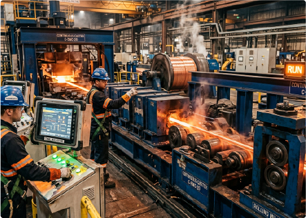
trial run
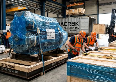
container load
workshop

Share your capacity, raw material and site conditions — we'll come back with a process route, equipment selection and a turnkey path to production.


No.310–311 National Road, Quanshan District, Xuzhou City, China
Check our FAQs below, or reach out to our team for tailored answers and project quotation.
Get a Quote